


Hydropower in the Philippines plays a significant role in the country's energy landscape, leveraging the nation's abundant water resources. The classification of hydropower systems can be based on various criteria, such as capacity, technology, and type of reservoir. Below is an overview of the classification of hydropower systems in the Philippines, along with references to more comprehensive resources.
Classification of Hydro Power System In the Philippines
1. Based on Capacity
- Large Hydropower Plants: Plants with a capacity of more than 10 megawatts (MW). Examples include the Magat Dam and the Pulangi River Hydro Electric Complex.
- Small/Mini-Hydropower Plants: Facilities with a capacity between 1 MW and 10 MW. These are often used to supply local communities and can be more environmentally friendly.
- Micro Hydropower Plants: Systems with a capacity of less than 1 MW. These are typically deployed in rural areas and can provide power to isolated communities.
2. Based on Technology
- Run-of-River Hydropower: This type utilizes the flow of the river without the need for a significant storage reservoir. It has a lower environmental impact but can be less reliable due to variable water flow.
- Storage Hydropower: These systems involve building a dam or reservoir to store water. They can produce power on demand and provide stability to the electric grid. Examples in the Philippines include the San Roque Dam.
- Pumped Storage: A variation of storage hydropower, where water is pumped to a higher elevation during low demand and released to generate electricity during peak demand. There are currently limited examples of this technology being executed in the Philippines.
3. Based on Development Type
- Privately Owned Hydropower: Many small to medium hydropower plants are developed by private companies, which often focus on local energy needs and opportunities for independent power producer agreements (IPPAs).
- Government-Owned Hydropower: Large facilities are often owned and operated by government entities, such as the National Power Corporation (NPC).
4. Based on Environmental Impact
- Eco-Friendly Hydropower: Small and micro hydropower systems that utilize local water resources with minimal environmental disruption.
- Conventional Hydropower: Larger systems that may have significant ecological footprints due to damming rivers and altering their natural flow.
The classification of hydropower systems in the Philippines reflects both the technological diversity and the strategic approaches to utilizing water resources for energy generation. As the country continues to pursue renewable energy sources, further development and diversification in hydropower technologies are expected.
Typical Components of Micro-Hydro Power Systems
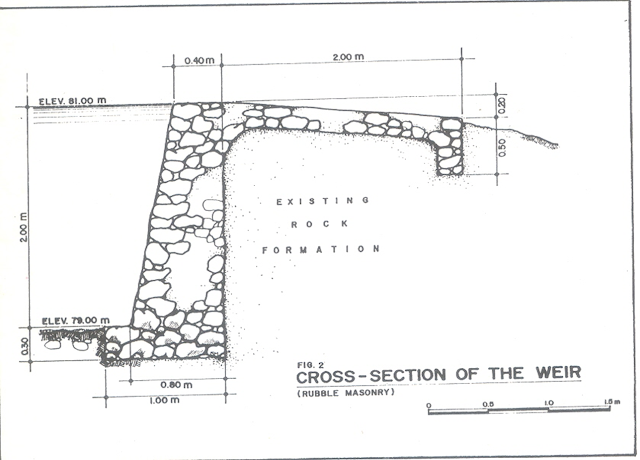
1. Weir- a structure built across the river to divert the flow, and raise or maintain the water level. It is also used as a temporary reservoir.
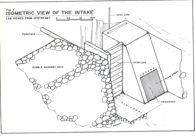
2. Intake- is an opening at the weir to divert the design discharge from the river to the power canal.
- it is a structure that facilitates the entry of water into the conduit system.
3. Settling basin- it is a structure designed to collect and flush sediments and other water-suspended materials to avoid entry to penstock and eventually to the turbine.
 |
| FIGURE 1 Image Source: http://micro-hydro-power.com/wp-content/uploads/2018/05/micro-hydro-power-diagram-hydroturbines-basics.jpg |
4. Headrace- conveys water from the intake to the forebay if it is an open canal or surge tank if it is a closed conduit.
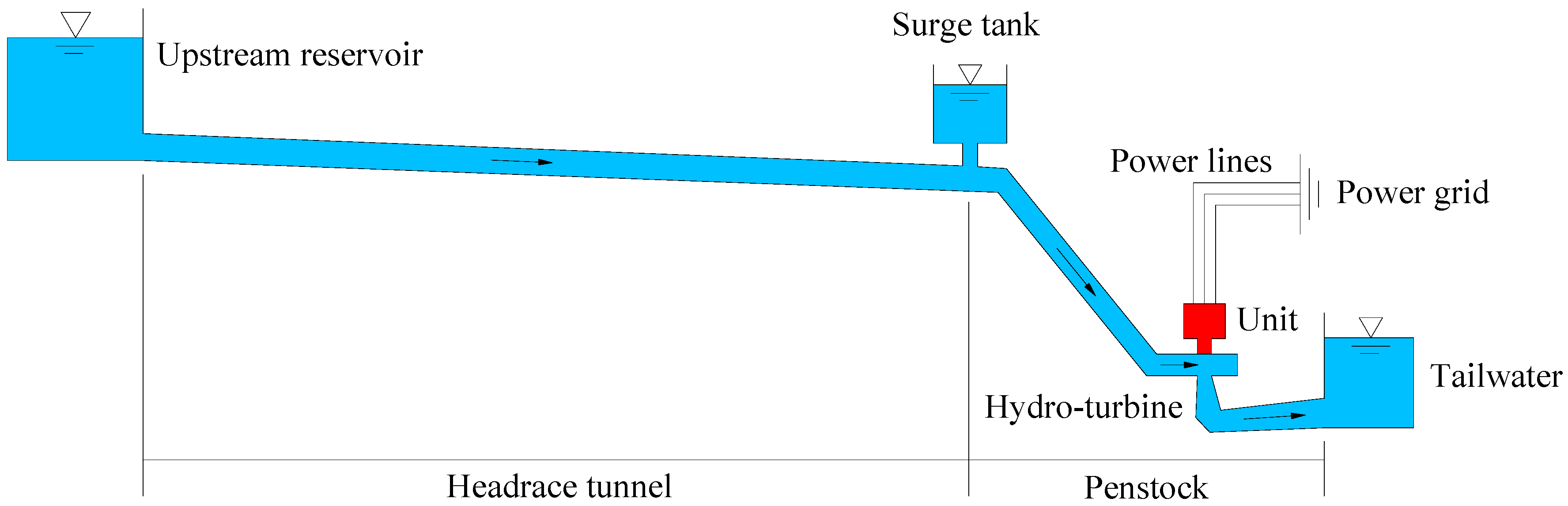 |
| FIGURE 2 Image Source: https://www.mdpi.com/energies/energies-11-02994/article_deploy/html/images/energies-11-02994-g001.png 5. Forebay/Surge tank- a structure that facilitates the entry of water to the penstock. This serves as a temporary reservoir during the start of the operation (see Figure 2) - Also function as the final settling basin for suspended matters in the water. |
6. Penstock- a pressure pipe that conveys water from the forebay/surge tank to the turbine (see Figure 1).
7. Powerhouse- structures in which the turbine, generator, and controls are housed.
8. Generator- an electrical machine that converts mechanical energy to electrical energy
9. Turbine - a hydraulic motor that converts the energy of water to mechanical energy
10. Distribution Line- are wires that convey electricity to consumers.
CLASSIFICATION OF WATER TURBINE
1. Reaction turbines are acted on by water, which changes pressure as it moves through the turbine and gives up its energy. They must be encased to contain the water pressure (or suction), or they must be fully submerged in the water flow.
2. Impulse turbines change the velocity of a water jet. The jet pushes on the turbine's curved blades which changes the direction of the flow. The resulting change in momentum (impulse) causes a force on the turbine blades. Since the turbine is spinning, the force acts through a distance (work) and the diverted water flow is left with diminished energy.
TYPES OF TURBINES
1. Pelton – - a free-jet impulse turbine used for high heads. - Usually used in large hydro

2. Cross Flow – an impulse turbine
- Having a drum-shape
- Can be used in high and low-head
- Usually used in MH


3. Francis turbine – a reaction turbine, that operates with filled water.


A. Mechanical application via belts or gears to run rice, feed, saw, and corn mills.
B. Electrical application via belts or gears to run a generator to produce electricity.
- Battery charging (run an alternator)
ADVANTAGES OF MICRO-HYDRO POWER SYSTEM
1. Power is produced at a fair rate
- there is little need for a storage bat.
- Power is available at any time
2. No fuel is required
3. Maintenance costs are low
4. Simple and robust, leading to lifetime of over 20 years without major new investment
5. No large dams, so that problems faced by large hydro, such as resettlement and reservoir siltation are avoided
6. No carbon dioxide and other hazardous gas emission
7. Little noise and little heat waste
METHOD IN MEASURING FLOW RATE
1. Bucket Method
- Involves recording the time required to fill a bucket or container of a predetermined size or volume.
- Suitable only for low discharge (less than 50 lps)
Example:
What is the flow rate of a stream if it takes 40 seconds to fill an 80-liter container?
Q = V/t = 80/40 = 2 lps
2. Weir Method
- an accurate method that can be used to measure the flow rate of any stream
- a temporary dam is built across the stream perpendicular to the flow, with a rectangular notch or spillway. The depth of flow above the notch is determined.
Flow rate can be determined by this formula:
Q = cLhn
Where; Q = flow rate, lps, cms
c = constant
L = length of notch , cm, m
h = depth of flow above the notch, cm,m
n = exponent depending on the shape of a notch
The following are some weir formulas
Rectangular : Q = 1.8 ( L – 0.2h) h³/²
Triangular : Q = 1.4h ^5/2
Trapezoidal : Q = 1.9 Lh³/²
3. Velocity-Area Method
- Used in larger streams and if done carefully and repeated several times can give accurate results
- requires determination of stream velocity and stream cross-sectional area at a point along a stream. The point should be relatively straight, smoothly flowing, and generally uniform in width.
Q = AV
Where; Q = flow rate, lps, cms
A = x-sectional area of the stream, cm^2, m^2
V = speed of water in the stream, cm per sec, mps
Determination of X-sectional area
The x-sectional area of the stream can be determined by dividing the x-section into sub areas. The width of the stream is determined and the average depth is measured
A = w x d
A = x-sectional area, m^2, cm^2
w = width of the stream , m, cm
d = average depth, m, cm
Determination of stream Velocity
1. Float Method
Easiest method but not accurate in irregular streambed profiles.
A length of the stream which is relatively straight and uniform is selected.
A floating object such as a piece of wood and a partially filled bottle is placed at the point in the stream where velocity is required.
The time t it takes to cover a distance d is recorded
Vs = C d/t
Where; V = velocity of stream, m/s, cm/s
d = distance traveled, m, cm.
t = time traveled, sec
C = correction factor for the type of streambed
C =0.60 for a stream with a rocky bed
= 0.85 for the stream with smooth bed
2. Current Meter
The most common method for measuring velocities at any depth in the larger stream or rivers that are not turbulence
A very accurate method of velocity measurement.
Requires a special kind of equipment
3. Velocity-head rod method
A vertical rod is placed in the point of the stream where the surface velocity is to be determined.
The rise of the stream ‘h’ above the original level of the stream is equal to the velocity head. Therefore
Vs = √2gh
4. Slope-Area Method
Uses an open channel flow equation such as Manning’s equation.
Vs = r2/3s1/2 /n
Where; Vs = average velocity in channel (m/s)
r = hydraulic radius = A/P
A = x-sectional area (sq. m)
P = wetted surface (m)
n = rough coefficients
To use this method, a straight channel 50-300 m long with a reasonably uniform slope and x-section should be selected. Its bed and bank should be permanent and the slope should be steep enough to be measured without a large percentage error. The slope of the channel is determined by the difference in water elevations. The roughness of the bed and banks would be estimated.
Roughness Coefficient

5. Salt Dilution Method
This involves the measuring of the dilution of salt release into a stream.
The change in concentration of salt in the stream over time as the water flows past a point downstream is determined.
A special probing instrument is used in this method
Head Measurement (H)
Using level (surveyors or carpenters)
Using clinometer
Using pressure gage (H = P/9.8)
Using altimeter
Power Calculation
Once you have determined the usable flow rate Q and the net head H, you are now in the position to calculate the amount of power you can expect.
Assuming 100% power available from the water, theoretical power (Pth) in kW
Pth = 9.8QH
Where; Pth = theoretical power in kW
Q = flow rate in cubic meters/sec
H = net head in meter
The useful power available can be determined by multiplying the theoretical power by the efficiency of the system. For micro-hydro system, typical efficiency is 60%
Pa = eff. X Pth = 9.8 eff QH
Where; Pa = available power in kW
Q = flow rate in cubic meters/sec
H = net head in meter
eff = system efficiency
References
1. Department of Energy (DOE) - Philippines (Official publications and statistics)
2. National Power Corporation (NPC) - reports and updates on hydropower projects
3. Renewable Energy Policy Framework in the Philippines - analyses on micro, small, and large hydropower initiatives
4. "Hydropower in the Philippines" - various articles and publications from local energy research institutions and international organizations focused on renewable energy.
.png)
.png)
.png)
0 Comments